
Catch the defect at the station, not in the field
Automated quality systems inspect and verify during production — machine vision, in-line gauging, torque and pressure verification, SPC on live process data — instead of relying on end-of-line sampling. They remove the worst property of manual inspection: it is exhausting, inconsistent, and statistically guaranteed to miss defects at any realistic volume.
Willowark engineers inspection around the defect, not the camera. We start from your defect Pareto and escape history, determine what measurement would catch each one, and then choose the method — 2D or 3D vision, laser measurement, load cells, electrical test. Lighting and fixturing get as much engineering as algorithms, because they decide whether vision works at all.
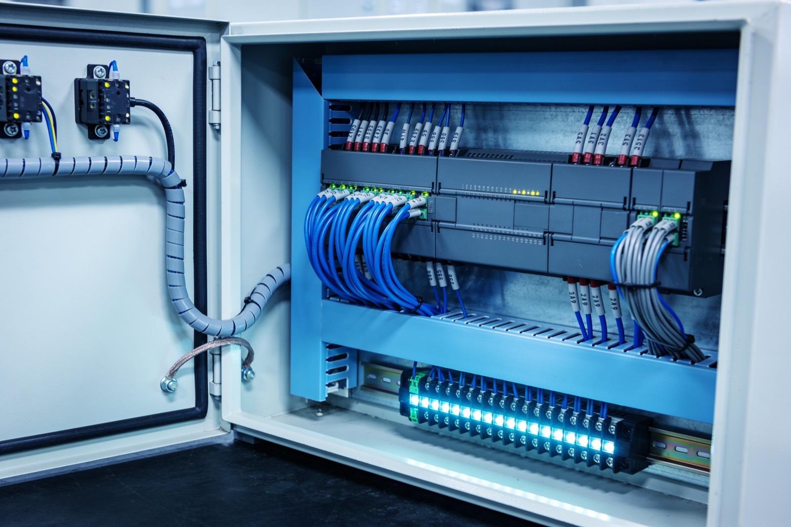 Industrial Automation
How the work gets done
The same way every time: scope, build, hand over.
A vision build involves optics and lighting design — backlight, dome, dark field, matched to the surface and the defect — camera and lens selection for the required resolution at line speed, and inspection logic ranging from classical tools like edge finding, blob analysis, and pattern matching to trained deep-learning models for defects that resist rule-based description. Results tie into the PLC over Ethernet/IP for real-time reject actuation, and every inspection is logged with images, so escapes can be investigated and limits tuned with evidence. SPC runs alongside: control charts on critical parameters, with alerts on trends before they become defects.
In production, the system is judged by both error rates: false rejects that throw away good parts and erode trust, and escapes that reach customers. We validate against a library of known-good and known-bad parts before go-live, run supervised production to tune thresholds, and report ongoing performance so quality can see the system working — gauge R&R thinking applied to automated inspection.
Scoping runs on real parts. We collect good and bad samples across the defect classes that matter, image them under candidate lighting and optics on a bench, and report what is reliably separable before a system is designed. The site walk covers what the bench cannot: line speed and part presentation, ambient light through nearby doors, vibration, space for a camera and lights, and how rejects will physically leave the line. From this comes a specification listing each defect, the method that catches it, the expected read window, and the pass and fail actions, reviewed with quality and production before any hardware is purchased.
What goes wrong in service is rarely the algorithm. Lighting drifts as LEDs age, a fixture loosens, a new supplier's part has a slightly different sheen, or a reject mechanism fails and bad parts pass through. We design against each: reference-target checks that flag drifting illumination, reject confirmation sensors, and logged images that make a change in parts visible immediately. Reject actuation runs through the PLC, with any pinch or motion hazard handled in safety-rated hardware. Commissioning happens at line speed during a planned run, and handover includes the inspection recipe, a tuning procedure, and training so quality staff can review results and adjust limits within agreed bounds.
Scope it in writing
What we agree before work starts
- Defect analysis and inspection method selection
- Vision system design: optics, lighting, fixturing, and software
Build with checkpoints
Working results, not slide decks
- PLC integration for real-time reject handling
- Image and result logging with retrieval for investigations
Hand over something you own
Documentation, source, and training
- Validation report against known-good and known-bad part libraries
- Inspection recipe documentation, tuning procedure, and quality-staff training
Sound familiar?
Where automated quality systems earns its keep.
A cosmetic defect that three inspectors catch at three different rates
A torque station with no record of whether the spec was actually met
A customer escape that a simple presence check would have caught
A molding process that drifts out of spec between hourly checks
Ask about Automated Quality Systems
Describe the problem. Get a straight answer.
One line is enough. An engineer replies within a business day.
Related work
Radar centering system for steel mills
Components:
- Radar sensors (strip position): Non-contact radar reading strip edge position in a hot, dusty, vibrating environment where optical sensors fail.
- Edge controller (signal processing): Turns raw radar returns into a clean lateral offset in real time.
- Mill PLC (centering actuators): The mill's existing controller: receives the offset and drives the centering actuators.
- Operator HMI (live position): Live strip position for the operator.
Connections:
- Radar sensors to Edge controller (raw returns)
- Edge controller to Mill PLC (offset)
- Edge controller to Operator HMI
A steel-mill systems provider · Steel manufacturing
Radar-based centering system for steel mills
End-to-end engineering of a radar sensing system that measures and centers material on steel mill lines — from equipment assessment through hardware selection, electrical engineering, software, installation, and commissioning.
Read the case study →Common questions
Asked before every automated quality systems project.
Can machine vision handle our defect, or is it too subtle?
The honest answer requires samples. Send us good and bad parts and we run a feasibility study with real optics and lighting before anyone buys a system. Many 'impossible' defects become straightforward with the right lighting geometry; a few genuinely are not vision problems, and we say so.
What happens to all the inspection images?
They are an asset. We store them with results — typically full images for failures and a sample of passes — with retention you control. That archive lets you investigate escapes, retune limits with evidence, and train better models later without waiting months to collect data.
Will automated inspection replace our quality inspectors?
It usually redeploys them. Automation handles the repetitive 100% checks humans do worst, while people move to the judgment work — disposition, root cause, supplier quality. Plants typically end up inspecting far more than before, with people doing the parts that actually need people.
What happens when we introduce a new part or product?
It depends on how different it is. Similar parts usually need a new recipe — a saved set of regions, limits, and reference images — which your trained staff can typically create with the tuning procedure we hand over. A part with a new geometry, surface, or defect class may need a feasibility check and possibly new lighting or fixturing. We design systems with recipe management from the start so product changes are a procedure, not a project.
How do we know the system is still working correctly months later?
By checking it the way you would check a gauge. We set up periodic verification with a known-bad reference part that must be rejected and a known-good one that must pass, along with logged false-reject and escape rates that quality reviews. Reference-target checks flag lighting drift automatically. If performance shifts, the image archive shows what changed — parts, lighting, or fixturing — so the fix is targeted rather than a full re-tune.

Where this sits
Automated Quality Systems, inside a industrial automation system.
The lit component is the part of the system this service delivers; the rest is what it has to work with.
Hover or focus a component to see what it is and what it talks to. Arrow keys move between them.
Sensors and machines report into the PLC; the PLC drives the HMI and publishes tags to a historian; the historian feeds dashboards and, where it exists, the MES.
Components:
- Machine (press, cell, line): The equipment itself. Newer machines expose tags; older ones need a sensor or a serial tap.
- Sensors (counts, temps, current): Retrofit sensors where the machine offers nothing: proximity counts, current transformers, temperature.
- PLC (control): The controller: logic, safety, and the tag table everything else reads.
- HMI (operator): Operator screen at the machine.
- Historian (tag store): Time-series store of PLC tags: uptime, counts, faults, cycle times.
- Dashboards (OEE, downtime): Plant TV and office views: OEE, downtime reasons, shift comparison.
- MES / ERP (orders): Work orders down, production counts up.
Connections:
- Sensors to PLC over 4-20mA
- Machine to PLC over EtherNet/IP
- PLC to HMI over EtherNet/IP
- PLC to Historian over OPC-UA
- Historian to Dashboards over REST
- Historian to MES / ERP over REST, both directions
Strategy. Software. Systems.
Have a system that should exist?
Tell us what your operation is doing manually, what isn't connected, or what you're trying to build. We'll tell you plainly whether and how we can help.