
One trustworthy signal built from many imperfect sensors
Every sensor fails in a predictable way: cameras go blind in glare and darkness, radar smears fine detail, GPS drops indoors, IMUs drift, encoders slip. Sensor fusion combines complementary sensors mathematically so the system's estimate stays trustworthy when any single input degrades — removing the brittleness that kills single-sensor designs in the field.
Willowark approaches fusion as estimation engineering, not glue code. We characterize each sensor's noise and failure behavior, synchronize everything on a common clock, and combine measurements through principled filters with quantified uncertainty — so downstream logic knows not just the answer, but how much to trust it.
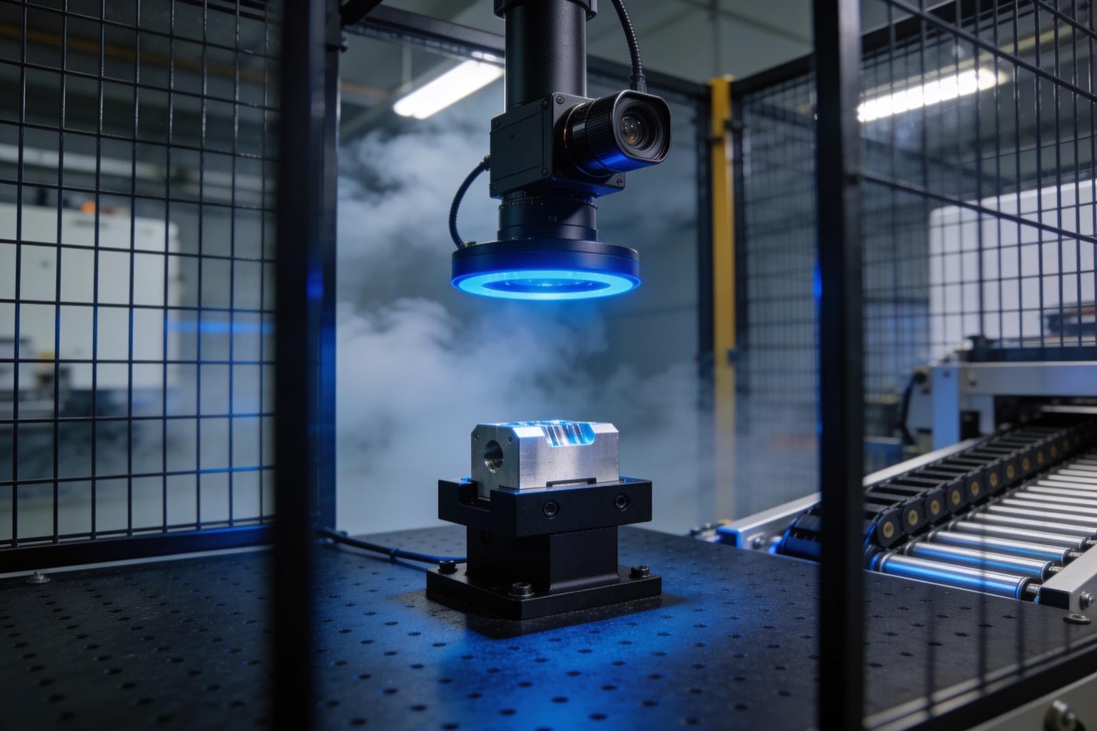 Vision & Advanced Sensing
How the work gets done
The same way every time: scope, build, hand over.
The foundation is time and space alignment: hardware timestamps and PTP synchronization so measurements from different sensors describe the same instant, and extrinsic calibration so they describe the same coordinate frame — fusing misaligned data produces confident nonsense. On that foundation sit the estimators: Kalman filters and their extended and unscented variants for tracking and localization, complementary filters where dynamics are simple, and factor-graph methods where trajectories matter. Outlier gating rejects the glitch measurements every real sensor produces, and covariance tuning is done against recorded data, not intuition.
Production readiness means testing against ground truth and, just as important, engineering the degraded modes: what the system does when the camera is blinded or the GPS drops, and how it reports its own confidence. We build logging and replay tooling into every fusion system, because the ability to re-run a field incident through the filter on a bench is what makes these systems debuggable rather than mysterious.
Feasibility starts with a recording, not a filter. Before proposing an architecture we instrument the candidate sensors, capture data through the operating conditions that matter — the glare hour, the loaded vehicle, the aisle where the GPS drops — and analyze it offline. That data tells us which sensors carry information in which conditions, how their errors correlate, and what update rates and latencies the estimator will see. It also settles the architecture: a loosely coupled design that fuses each sensor's output is simpler and easier to debug, while tightly coupled fusion of raw measurements buys robustness at the cost of complexity. We choose the simplest structure that meets the requirement.
Implementation targets the compute you have — embedded processor, industrial PC, or microcontroller — and the filter is written for fixed-rate, bounded-latency execution rather than as a research script. Calibration does not stay put, because mounts shift, lenses get replaced, and wheels wear, so we build in health monitoring that watches innovation statistics and flags a sensor whose measurements have stopped agreeing with the rest, along with a documented re-calibration procedure. The system is handed over with source, the recorded datasets, the replay tooling, and a written description of the model and its tuning, so your engineers can extend it rather than treat it as a black box.
Scope it in writing
What we agree before work starts
- Sensor suite analysis with noise and failure-mode characterization
- Time synchronization and extrinsic calibration design
Build with checkpoints
Working results, not slide decks
- Fusion filter implementation with documented uncertainty estimates
- Degraded-mode behavior design for sensor dropout
Hand over something you own
Documentation, source, and training
- Logging and replay tooling for field debugging
- Validation against ground-truth or reference measurements
Sound familiar?
Where sensor fusion earns its keep.
AGV and mobile robot localization from wheel odometry, IMU, and lidar
Camera-plus-radar object tracking in yards and outdoor facilities
Condition monitoring that fuses vibration, current, and temperature
Precision docking and positioning from multiple ranging sensors
Ask about Sensor Fusion
Describe the problem. Get a straight answer.
One line is enough. An engineer replies within a business day.
Related work
Radar centering system for steel mills
Components:
- Radar sensors (strip position): Non-contact radar reading strip edge position in a hot, dusty, vibrating environment where optical sensors fail.
- Edge controller (signal processing): Turns raw radar returns into a clean lateral offset in real time.
- Mill PLC (centering actuators): The mill's existing controller: receives the offset and drives the centering actuators.
- Operator HMI (live position): Live strip position for the operator.
Connections:
- Radar sensors to Edge controller (raw returns)
- Edge controller to Mill PLC (offset)
- Edge controller to Operator HMI
A steel-mill systems provider · Steel manufacturing
Radar-based centering system for steel mills
End-to-end engineering of a radar sensing system that measures and centers material on steel mill lines — from equipment assessment through hardware selection, electrical engineering, software, installation, and commissioning.
Read the case study →Common questions
Asked before every sensor fusion project.
When is sensor fusion actually worth the complexity?
When one sensor cannot meet the requirement across all operating conditions — outdoor perception, indoor localization, or any measurement that must survive a sensor's bad day. If a single well-chosen sensor does the job, we will tell you so; fusion earns its complexity only when the failure modes demand it.
How do you validate a fusion system?
Against ground truth: surveyed positions, motion-capture or RTK references, or instrumented test scenarios, plus deliberate sensor-denial tests where we blind or disconnect inputs and verify graceful degradation. Recorded datasets let us replay every scenario through filter changes, so improvements are measured rather than assumed.
Can you add fusion to sensors we already have?
Usually, with one caveat: timing. Fusion quality depends on knowing when each measurement was taken, so existing sensors may need hardware trigger or timestamp upgrades. We audit your current sensors' interfaces and latencies first and tell you what is usable as-is and what needs a change.
Do you use ROS, or do you write fusion from scratch?
Whichever fits the deployment. ROS 2 and its ecosystem are a productive base for mobile robots and research-adjacent systems, and we use them where they fit; for products, embedded targets, or plants that will not maintain a ROS stack, we write lean filters in C++ against the specific sensors. Either way the estimator itself is ours to explain and yours to keep, with the math documented independent of the framework.
How much compute does sensor fusion need?
Usually less than people assume. A Kalman filter tracking a few dozen states runs comfortably on a microcontroller; the heavy cost is typically the perception in front of it — camera or lidar processing — not the fusion itself. Factor-graph and multi-object tracking methods need more, and we size the processor after profiling the actual pipeline on recorded data rather than guessing. If the budget is tight, we simplify the model before we upgrade the hardware.


Where this sits
Sensor Fusion, inside a vision & advanced sensing system.
The lit component is the part of the system this service delivers; the rest is what it has to work with.
Hover or focus a component to see what it is and what it talks to. Arrow keys move between them.
A part is presented under controlled lighting, a camera captures a frame per trigger, inspection compute decides, the PLC rejects, and every result lands in a database that feeds SPC dashboards.
Components:
- Part (on conveyor): Presentation is half the problem: fixturing, orientation and cycle time decide what is possible.
- Lighting (ring / backlight): Chosen for the defect, not the camera. Lighting is where most vision projects are won or lost.
- Camera (GigE, triggered): Machine vision camera, hardware-triggered per part.
- Inspection compute (edge PC): Runs the inspection — classical tools, a trained model, or both — within cycle time.
- Line PLC (reject / accept): Acts on the verdict: reject gate, line stop, or count.
- Results DB (every part): Every inspection result, with the image reference, for traceability and SPC.
- SPC dashboard (trends): Escape rate, false-reject rate and drift over time.
Connections:
- Part to Camera over digital I/O (trigger)
- Lighting to Camera
- Camera to Inspection compute over GigE
- Inspection compute to Line PLC over digital I/O
- Inspection compute to Results DB over SQL
- Results DB to SPC dashboard over REST
Strategy. Software. Systems.
Have a system that should exist?
Tell us what your operation is doing manually, what isn't connected, or what you're trying to build. We'll tell you plainly whether and how we can help.