
Software that turns pixels and point clouds into numbers you can defend
Cameras and 3D sensors produce data; metrology software turns that data into measurements with stated uncertainty — dimensions your quality department can put on a certificate. It removes the gap between an impressive-looking scan and a number you would defend in a customer audit.
Willowark builds measurement software calibration-first. Every measurement chain is anchored to certified artifacts, validated like a gauge with repeatability studies, and designed so an operator cannot accidentally produce an untraceable result. The pretty visualization comes last; the uncertainty budget comes first.
 Vision & Advanced Sensing
How the work gets done
The same way every time: scope, build, hand over.
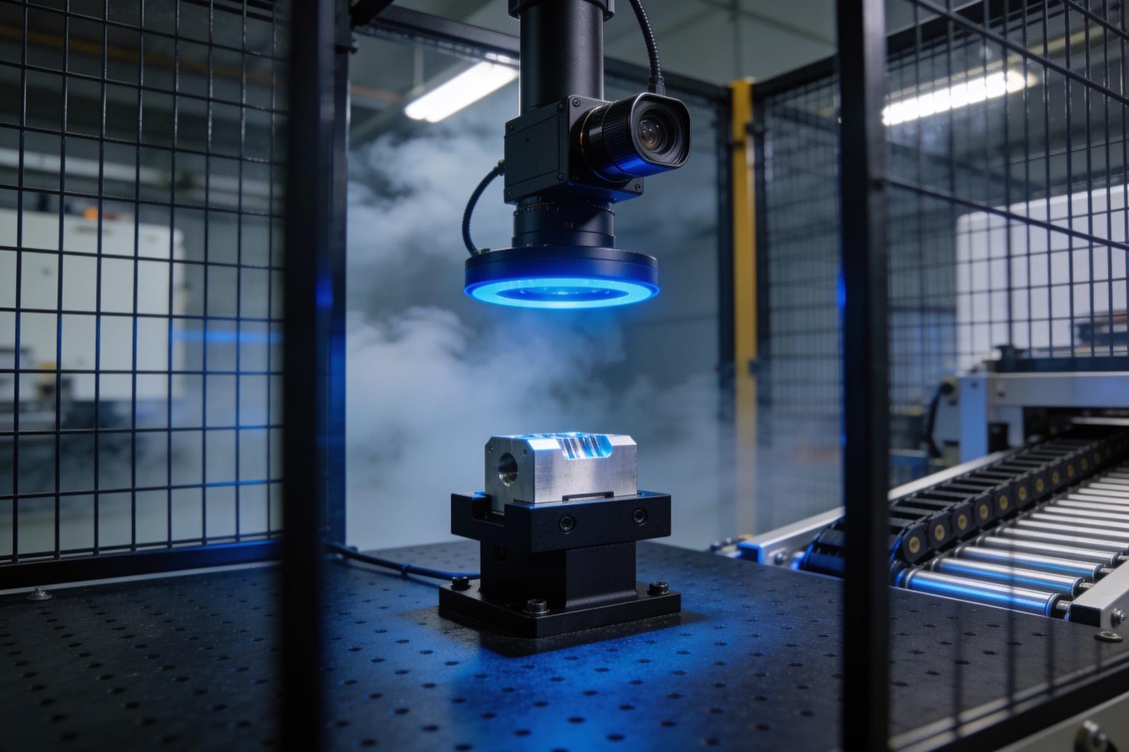
Image-based measurement lives or dies at the subpixel level: edge-detection algorithms that locate boundaries to a tenth of a pixel, lens distortion models that flatten the field, and telecentric calibration where perspective would bias results. Scale comes from certified calibration artifacts, with temperature compensation where thermal growth of parts or fixtures matters at your tolerances. For 3D data, the toolbox extends to least-squares and minimum-zone fitting of planes, cylinders, and freeform surfaces, and GD&T evaluations — flatness, position, profile — computed the way your drawings define them.
Software earns production trust through gauge studies. We run gauge R&R across operators and parts, correlate results against your CMM or reference instruments, and document measurement uncertainty before the system makes accept/reject decisions. Results export wherever your quality system lives — CSV, QIF, or direct database and SPC integration — with audit trails tying every number to a part, recipe version, and calibration state.
Before writing measurement code we work through the drawing feature by feature and ask, for each tolerance, whether the imaging chain can resolve it with margin. The usual rule of thumb is that the measurement system should consume only a modest fraction of the tolerance, and that sets the pixel size, lens type, and field of view — often forcing a choice between one wide view that sees the whole part and several narrow views that measure it properly. We run trial measurements on real parts against reference values during feasibility and report which features are measurable, which are marginal, and which should stay on a contact gauge.
The software is structured so a result can be explained. Each measurement recipe is versioned, and alongside the audit trail a result stores its image and intermediate values — the fitted edges or planes — so a disputed number can be reconstructed months later. Operator workflows are narrow: load a part, scan a traveler, run, read the result; parameters that affect the measurement sit behind a role-based lock. A control chart on the daily master-part check catches drift in scale or focus before it reaches production data. Source code, build instructions, and a developer guide come with the system, because measurement software you cannot modify eventually becomes measurement software you cannot trust.
Scope it in writing
What we agree before work starts
- Measurement requirements analysis mapped to your drawings and tolerances
- Calibration design anchored to certified reference artifacts
Build with checkpoints
Working results, not slide decks
- Measurement application with operator-proof workflows
- Gauge R&R study and CMM correlation report
Hand over something you own
Documentation, source, and training
- SPC and quality-system integration with audit trails
- Uncertainty documentation and calibration procedures
Sound familiar?
Where measurement & metrology software earns its keep.
Replacing manual optical comparator checks with automated stations
In-line dimensional measurement feeding live SPC
Automated incoming inspection of supplier parts
Measurement engines embedded inside OEM instruments
Ask about Measurement & Metrology Software
Describe the problem. Get a straight answer.
One line is enough. An engineer replies within a business day.
Related work
Radar centering system for steel mills
Components:
- Radar sensors (strip position): Non-contact radar reading strip edge position in a hot, dusty, vibrating environment where optical sensors fail.
- Edge controller (signal processing): Turns raw radar returns into a clean lateral offset in real time.
- Mill PLC (centering actuators): The mill's existing controller: receives the offset and drives the centering actuators.
- Operator HMI (live position): Live strip position for the operator.
Connections:
- Radar sensors to Edge controller (raw returns)
- Edge controller to Mill PLC (offset)
- Edge controller to Operator HMI
A steel-mill systems provider · Steel manufacturing
Radar-based centering system for steel mills
End-to-end engineering of a radar sensing system that measures and centers material on steel mill lines — from equipment assessment through hardware selection, electrical engineering, software, installation, and commissioning.
Read the case study →Common questions
Asked before every measurement & metrology software project.
How is traceability maintained in a custom measurement system?
Through the calibration chain: the system is scaled against certified artifacts with documented calibration procedures and intervals, and every measurement records which calibration state produced it. That gives you an unbroken line from a production measurement back to a certified standard — the same logic as any traceable gauge.
Will the results match our CMM?
That is a validation question we answer with data, not assurance. During commissioning we run correlation studies measuring the same parts on both systems and quantify bias and spread. Optical and contact methods can legitimately differ on some features — edges, form errors — and we document where and why so the systems can coexist honestly.
Can the software integrate with our existing quality systems?
Yes. Typical integrations push per-part results into SPC packages, MES, or quality databases, export QIF or CSV for tools that expect files, and expose live values to PLCs for in-process limits. We treat the export format as a requirement gathered up front, not a feature bolted on later.
Can you certify the system for our customer's quality requirements?
We do not issue certifications; that is the role of your quality system and, where applicable, accredited labs. What we provide is the evidence your quality system and auditors typically ask for: documented calibration to certified artifacts, gauge R&R results, an uncertainty budget, correlation data, and audit trails. Those records are what allow your quality team to qualify the system under your own procedures, whether that is an internal MSA process or a customer-specific requirement.
Can the measurement software run inside our own product or machine?
Yes, and it is a common request from OEMs. The measurement engine is built as a library with a documented API, separate from any HMI, so it can be embedded in your instrument or machine software and called from your code. We agree licensing and source terms up front, provide the calibration routines your production line will need to run on each unit, and deliver the validation data so your own product qualification can reference it.


Where this sits
Measurement & Metrology Software, inside a vision & advanced sensing system.
The lit component is the part of the system this service delivers; the rest is what it has to work with.
Hover or focus a component to see what it is and what it talks to. Arrow keys move between them.
A part is presented under controlled lighting, a camera captures a frame per trigger, inspection compute decides, the PLC rejects, and every result lands in a database that feeds SPC dashboards.
Components:
- Part (on conveyor): Presentation is half the problem: fixturing, orientation and cycle time decide what is possible.
- Lighting (ring / backlight): Chosen for the defect, not the camera. Lighting is where most vision projects are won or lost.
- Camera (GigE, triggered): Machine vision camera, hardware-triggered per part.
- Inspection compute (edge PC): Runs the inspection — classical tools, a trained model, or both — within cycle time.
- Line PLC (reject / accept): Acts on the verdict: reject gate, line stop, or count.
- Results DB (every part): Every inspection result, with the image reference, for traceability and SPC.
- SPC dashboard (trends): Escape rate, false-reject rate and drift over time.
Connections:
- Part to Camera over digital I/O (trigger)
- Lighting to Camera
- Camera to Inspection compute over GigE
- Inspection compute to Line PLC over digital I/O
- Inspection compute to Results DB over SQL
- Results DB to SPC dashboard over REST
Strategy. Software. Systems.
Have a system that should exist?
Tell us what your operation is doing manually, what isn't connected, or what you're trying to build. We'll tell you plainly whether and how we can help.