
Put a camera on every part instead of sampling one in fifty
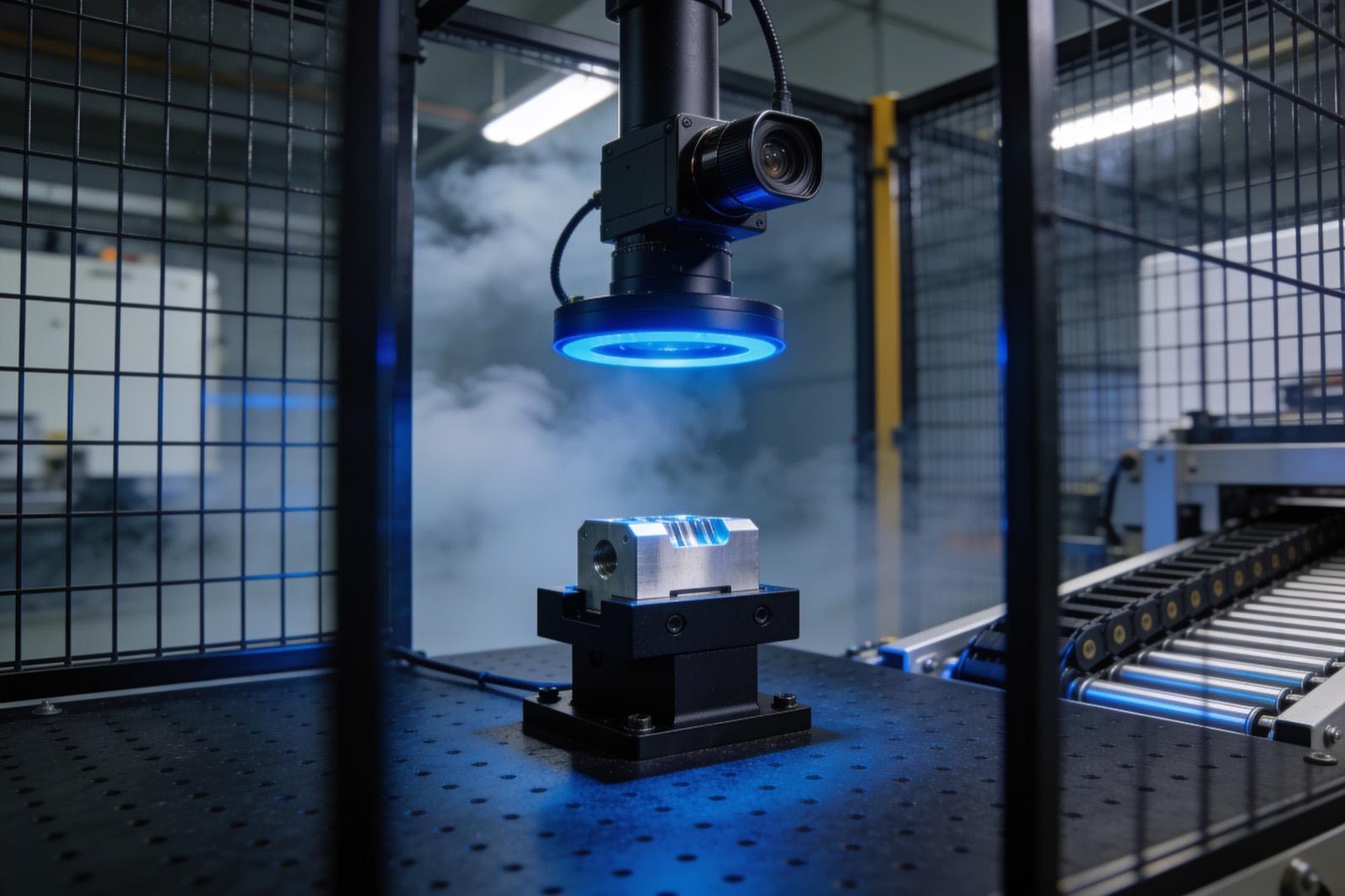
Automated visual inspection replaces sampled, manual quality checks with camera-based inspection of every single part your line produces. The problem it removes is escapes: the defective parts that slip through because a human can only look at so many pieces, for so many hours, before attention fades.
Willowark builds inspection stations around your actual defect library. We collect real rejects, run bench imaging trials to prove each defect class is visible, and write acceptance criteria down before any hardware is ordered. That discipline is what separates an inspection system your operators trust from one they learn to bypass.
 Vision & Advanced Sensing
How the work gets done
The same way every time: scope, build, hand over.
The build depends on the product. Discrete parts usually call for area-scan cameras triggered by encoder pulses; continuous webs, extrusions, and cylindrical parts often need line-scan cameras that image thousands of lines per second as material moves past. Each defect class gets the lighting that reveals it — darkfield for scratches, backlighting for edge chips and short shots, coaxial light for print and surface texture. Detected defects are classified, logged, and tied to a physical reject: an air blast, diverter, or flagged stop, with a downstream verification sensor confirming the bad part actually left the line.
Production success is measured the way your quality team measures anything: escape rate, false-reject rate, and repeatability. We run gauge-style trials with seeded defect sets before handover and archive inspection images so every reject decision can be audited. When you add a SKU, the recipe system handles it — new parameters, not a new project.
Part presentation decides more inspection outcomes than the camera does. A part that tumbles, rotates, or sits at a slightly different height every cycle forces wider tolerance windows and more false calls, so we spend real effort on the mechanics: guides, nests, and timing screws that put every part in the same pose, or, where that is impractical, imaging that tolerates the variation you actually have. Sometimes the right answer is a second camera instead of a better fixture. We make that trade-off with you during feasibility, with cost and floor space on the table, rather than discovering it during commissioning.
An inspection station generates a lot of data, and what you do with it is part of the design. Per-part results, images of rejects, and periodic images of passing parts go to storage with a retention policy you choose, indexed by lot, shift, and recipe so quality engineers can pull a day's rejects in seconds. Trend reports on reject rate by defect class often reveal an upstream process problem before anyone notices it. When reject rates shift without a process change, that is the signal to re-check lighting output, lens cleanliness, and thresholds against a reference set — a drift check we build into the maintenance schedule.
Scope it in writing
What we agree before work starts
- Defect library review and bench imaging feasibility report
- Inspection station design: cameras, lighting, mechanics, and guarding
Build with checkpoints
Working results, not slide decks
- Inspection software with defect classification and recipe management
- Reject mechanism integration with verification sensing
Hand over something you own
Documentation, source, and training
- Seeded-defect validation trials with documented escape and false-reject rates
- Operator training and maintenance documentation
Sound familiar?
Where automated visual inspection earns its keep.
Container, cap, and seal inspection on filling lines
Surface defect detection on extruded or rolled product
Weld and braze joint verification before assembly
Kit and package completeness checks before case packing
Ask about Automated Visual Inspection
Describe the problem. Get a straight answer.
One line is enough. An engineer replies within a business day.
Related work
Radar centering system for steel mills
Components:
- Radar sensors (strip position): Non-contact radar reading strip edge position in a hot, dusty, vibrating environment where optical sensors fail.
- Edge controller (signal processing): Turns raw radar returns into a clean lateral offset in real time.
- Mill PLC (centering actuators): The mill's existing controller: receives the offset and drives the centering actuators.
- Operator HMI (live position): Live strip position for the operator.
Connections:
- Radar sensors to Edge controller (raw returns)
- Edge controller to Mill PLC (offset)
- Edge controller to Operator HMI
A steel-mill systems provider · Steel manufacturing
Radar-based centering system for steel mills
End-to-end engineering of a radar sensing system that measures and centers material on steel mill lines — from equipment assessment through hardware selection, electrical engineering, software, installation, and commissioning.
Read the case study →Common questions
Asked before every automated visual inspection project.
Will automated inspection flood us with false rejects?
Not if thresholds are set against real production variation rather than golden samples. We tune the system using parts from multiple shifts and lots, then track false-reject rate as a first-class metric during commissioning. A small, known false-reject rate is normal; an untracked one is how systems get switched off.
Can it keep up with our line speed?
Speed drives the design, not the other way around. We calculate exposure times, transfer bandwidth, and processing budgets against your fastest rate, and select line-scan or high-frame-rate area-scan hardware accordingly. If a single station cannot keep up, we parallelize or split inspections across stations.
What happens when we introduce a new product?
The software is built around recipes: per-SKU parameters for regions of interest, thresholds, and reject rules. Adding a variant of an existing product is usually a configuration exercise your team can do. A genuinely new geometry may need an imaging check first, which we can run on sample parts.
Can automated inspection replace our human inspectors entirely?
Usually it replaces the repetitive looking, not the judgment. The system handles every part consistently at line speed; people move to reviewing borderline calls, auditing the system against seeded samples, and investigating why a defect class is rising. Some cosmetic or subjective criteria remain hard to automate, and we will tell you which ones during feasibility rather than promising a fully unattended line that you later have to staff anyway.
How do you handle a defect we didn't have samples for?
Honestly: the system cannot be validated against a defect it has never seen. If a new defect type appears after handover, the archived images usually contain examples, and we or your engineers add a detection tool or retrain against them, then re-run the seeded validation. For rule-based tools this is often a short configuration change; for learned models it is a retraining cycle. Either way, the recipe and validation records are updated so the change is traceable.


Where this sits
Automated Visual Inspection, inside a vision & advanced sensing system.
The lit component is the part of the system this service delivers; the rest is what it has to work with.
Hover or focus a component to see what it is and what it talks to. Arrow keys move between them.
A part is presented under controlled lighting, a camera captures a frame per trigger, inspection compute decides, the PLC rejects, and every result lands in a database that feeds SPC dashboards.
Components:
- Part (on conveyor): Presentation is half the problem: fixturing, orientation and cycle time decide what is possible.
- Lighting (ring / backlight): Chosen for the defect, not the camera. Lighting is where most vision projects are won or lost.
- Camera (GigE, triggered): Machine vision camera, hardware-triggered per part.
- Inspection compute (edge PC): Runs the inspection — classical tools, a trained model, or both — within cycle time.
- Line PLC (reject / accept): Acts on the verdict: reject gate, line stop, or count.
- Results DB (every part): Every inspection result, with the image reference, for traceability and SPC.
- SPC dashboard (trends): Escape rate, false-reject rate and drift over time.
Connections:
- Part to Camera over digital I/O (trigger)
- Lighting to Camera
- Camera to Inspection compute over GigE
- Inspection compute to Line PLC over digital I/O
- Inspection compute to Results DB over SQL
- Results DB to SPC dashboard over REST
Strategy. Software. Systems.
Have a system that should exist?
Tell us what your operation is doing manually, what isn't connected, or what you're trying to build. We'll tell you plainly whether and how we can help.