
Machine vision systems that catch what manual inspection misses
A machine vision system uses industrial cameras, engineered lighting, and image-processing software to inspect, measure, sort, or guide parts automatically. It replaces the slowest and least repeatable step in most quality processes — a person staring at parts — with an inspection that runs at line speed, never fatigues, and logs every result.
Willowark designs vision systems from the physics up. We start with the defect or dimension you need to detect, work out the resolution and contrast required to see it reliably, and only then select cameras, lenses, and lighting. The software, whether classical algorithms or deep learning, is built to run unattended on your floor, handshaking with PLCs and rejecting parts in real time.
 Vision & Advanced Sensing
How the work gets done
The same way every time: scope, build, hand over.
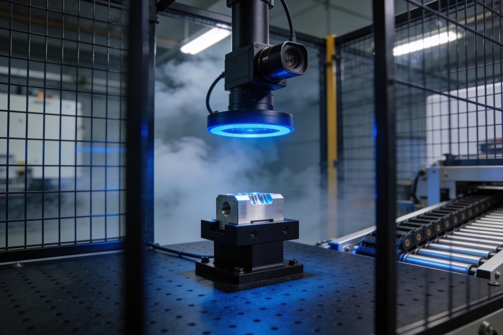
The engineering starts with optics: field-of-view and pixel-resolution math, lens selection — including telecentric optics when perspective error would corrupt a measurement — and lighting geometry. Backlights produce clean silhouettes, dome lights kill glare on shiny parts, and low-angle darkfield makes surface scratches jump out. Cameras connect over GigE Vision or USB3 Vision and are hardware-triggered from encoders or photo-eyes so every image is captured at the same position. Processing runs on an industrial PC or smart camera, and results pass to the PLC over EtherNet/IP or PROFINET to fire a reject gate inside a fixed time budget.
In production, success is measured in escape rate and false-reject rate, not demo images. We validate against known-good and known-defect part sets before handover, tune thresholds with your quality team, and archive every inspection image and result so disputes and drift can be diagnosed later. Operators get a clear HMI; your engineers get remote access, configuration backups, and real documentation.
Before any hardware is quoted, we run a bench feasibility phase with your parts. A handful of good pieces and every reject you can find go under candidate lighting and lens combinations on our bench, and the result is a short report with example images, the detection approach we would use, and an honest statement of what is and is not visible. Sometimes the answer is that a defect needs a different sensing method, or that two lighting setups are required. Learning that on a bench costs a few weeks; learning it after the enclosure is built costs the project.
Most inspections are solved with classical tools — edge detection, blob analysis, pattern matching, calibrated measurement — because they are fast, explainable, and easy for your engineers to adjust. We reach for deep learning when the defect is easy to see but hard to describe, and we say so in the design rather than defaulting to it. The software is delivered with source, a configuration structure your team can read, and a written explanation of what each tool does and why its parameters are set where they are. Handover is not finished until your engineer can change a threshold, add a region, and back up the configuration without calling us.
Scope it in writing
What we agree before work starts
- Feasibility study with sample-part imaging and detection benchmarks
- Complete vision hardware design: camera, lens, lighting, and mounting
Build with checkpoints
Working results, not slide decks
- Image-processing application with operator HMI
- PLC integration for triggering, results, and reject control
Hand over something you own
Documentation, source, and training
- Validation report against known-good and known-defect part sets
- Documentation, spares list, and on-site commissioning
Sound familiar?
Where machine vision systems earns its keep.
Verifying label presence, position, and print quality on packaging lines
Checking assembly completeness before parts leave a cell
Measuring critical dimensions on machined parts in-line
Guiding a robot to pick or place parts from a moving conveyor
Ask about Machine Vision Systems
Describe the problem. Get a straight answer.
One line is enough. An engineer replies within a business day.
Related work
Radar centering system for steel mills
Components:
- Radar sensors (strip position): Non-contact radar reading strip edge position in a hot, dusty, vibrating environment where optical sensors fail.
- Edge controller (signal processing): Turns raw radar returns into a clean lateral offset in real time.
- Mill PLC (centering actuators): The mill's existing controller: receives the offset and drives the centering actuators.
- Operator HMI (live position): Live strip position for the operator.
Connections:
- Radar sensors to Edge controller (raw returns)
- Edge controller to Mill PLC (offset)
- Edge controller to Operator HMI
A steel-mill systems provider · Steel manufacturing
Radar-based centering system for steel mills
End-to-end engineering of a radar sensing system that measures and centers material on steel mill lines — from equipment assessment through hardware selection, electrical engineering, software, installation, and commissioning.
Read the case study →Common questions
Asked before every machine vision systems project.
How do you decide between a smart camera and a PC-based vision system?
Smart cameras suit single, well-bounded inspections at moderate speeds — one part type, one or two checks, tight budget. PC-based systems win when you need multiple cameras, high frame rates, deep learning inference, or complex measurement logic. We prototype the inspection first, then pick the smallest platform that solves it with margin.
What do you need from us to scope a vision project?
Sample parts — both good ones and real rejects — plus line speed, available mounting space, and your pass/fail criteria in writing. With those we can run bench imaging trials and tell you honestly whether the defect is detectable before you commit to a full build.
Can a vision system handle normal part-to-part variation?
Yes, if the system is designed for it. We characterize your process variation during feasibility and build tolerance windows, normalization, or trained models around it. A system tuned only on golden samples will drown you in false rejects, which is why we insist on imaging real production parts early.
How long does a typical machine vision project take?
It varies with how many inspections, how much mechanical work, and how fast the feasibility answer is clear. A single-camera station with a straightforward defect typically runs a few weeks of feasibility followed by a couple of months of build, integration, and commissioning; multi-camera or measurement systems take longer. We give a schedule estimate after feasibility, when the design is actually known, rather than guessing before it.
Who maintains the system after handover?
Your team, with us available when needed. We design for that: configuration lives in files your engineers can back up and restore, the HMI exposes the adjustments operators legitimately need and locks the ones they should not touch, and the documentation covers lighting replacement, lens cleaning, and re-verification with a reference part set. Support agreements are available for remote diagnosis and periodic health checks, but the system does not depend on us to keep running.


Where this sits
Machine Vision Systems, inside a vision & advanced sensing system.
The lit component is the part of the system this service delivers; the rest is what it has to work with.
Hover or focus a component to see what it is and what it talks to. Arrow keys move between them.
A part is presented under controlled lighting, a camera captures a frame per trigger, inspection compute decides, the PLC rejects, and every result lands in a database that feeds SPC dashboards.
Components:
- Part (on conveyor): Presentation is half the problem: fixturing, orientation and cycle time decide what is possible.
- Lighting (ring / backlight): Chosen for the defect, not the camera. Lighting is where most vision projects are won or lost.
- Camera (GigE, triggered): Machine vision camera, hardware-triggered per part.
- Inspection compute (edge PC): Runs the inspection — classical tools, a trained model, or both — within cycle time.
- Line PLC (reject / accept): Acts on the verdict: reject gate, line stop, or count.
- Results DB (every part): Every inspection result, with the image reference, for traceability and SPC.
- SPC dashboard (trends): Escape rate, false-reject rate and drift over time.
Connections:
- Part to Camera over digital I/O (trigger)
- Lighting to Camera
- Camera to Inspection compute over GigE
- Inspection compute to Line PLC over digital I/O
- Inspection compute to Results DB over SQL
- Results DB to SPC dashboard over REST
Strategy. Software. Systems.
Have a system that should exist?
Tell us what your operation is doing manually, what isn't connected, or what you're trying to build. We'll tell you plainly whether and how we can help.